Arduino LED Sequential Control
— arduino — 7 min read
Arduino LED Sequential Control
What is Arduino?
Arduino is an open-source electronics platform, designed like building blocks:
-
Hardware: Physical components you can touch (like Arduino boards)
-
Software: Programs that control the hardware (Arduino IDE and code)
-
Both are part of electronics: The study of controlling electron movement
Why do we learn concepts of controlling electronics through Arduino?
-
Beginner-friendly with easy-to-use components
-
Rich learning resources and simple programming interface
-
Inexpensive compared to other platforms
-
Great for hands-on learning of electronics basics
What is a Microcontroller?
-
Like a mini computer brain
-
Can process inputs and control outputs
-
Perfect for controlling electronic devices
-
Arduino UNO R3 is a popular microcontroller board
Let's review some basic concepts of electronics.
Atomic Structure and Electrons:
-
Everything in our world is made up of atoms
-
Inside atoms, there are electrons that can move around
-
The movement of electrons creates electric current
-
Electronics is the study of how to control and use these electron movements

Electric Field and Force:
-
Electric field is created by uneven distribution of electrons
-
Places with extra electrons become negatively charged
-
Places lacking electrons become positively charged
-
This difference creates electric force (like magnets attracting or repelling)
-
When we create a path, electrons flow from negative to positive
Understanding Electrical Properties
Think of it like water flowing in a pipe:
-
Current (measured in Amperes or "Amps")
-
Amount of electron flow
-
Like the amount of water flowing
-
-
Voltage (measured in Volts)
-
The electric "pressure" pushing electrons
-
Like the height difference in a waterfall
-
When we say "1.5V battery", we mean there's a 1.5-volt potential difference between its positive and negative terminals
-
-
Resistance (measured in Ohms)
-
Controls how easily electrons can flow
-
Like the size of the pipe restricting water flow
-
Ohm’s Law: Relationship between voltage, current, and resistance
$V=I \times R$
Circuit:
-
Electricity needs a complete path (circuit)
-
Electrons flow from negative to positive to complete the loop
-
Like a race track with no breaks
How to build LED Sequential Control with Arduino?
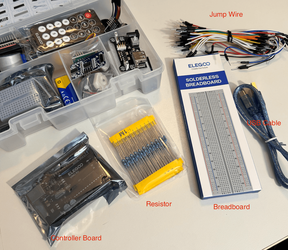
Arduino Board: Acts as the "brain" of the system
-
Provides programming control and power management
-
Receives 5V power and programs via USB
-
Contains multiple pins:
-
Digital Pins: for input/output
-
Analog Pins: for input/output
-
Power Pins: 5V, 3.3V
-
Ground Pins: reference point (0V)
-
Breadboard: A tool for quick electronic component connections
-
No soldering required, reusable
-
Specific connection patterns:
-
Power rails (sides): connected vertically
-
Center area: every five holes connected horizontally
-
Middle gap: separates upper and lower sections
-
+ + + + + + + + + + ← Power Rail (Positive)- - - - - - - - - - ← Power Rail (Negative)
○ ○ ○ ○ ○ | ○ ○ ○ ○ ○○ ○ ○ ○ ○ | ○ ○ ○ ○ ○○ ○ ○ ○ ○ | ○ ○ ○ ○ ○ ← Center area○ ○ ○ ○ ○ | ○ ○ ○ ○ ○○ ○ ○ ○ ○ | ○ ○ ○ ○ ○
← Middle gap
○ ○ ○ ○ ○ | ○ ○ ○ ○ ○○ ○ ○ ○ ○ | ○ ○ ○ ○ ○○ ○ ○ ○ ○ | ○ ○ ○ ○ ○ ← Center area○ ○ ○ ○ ○ | ○ ○ ○ ○ ○○ ○ ○ ○ ○ | ○ ○ ○ ○ ○
+ + + + + + + + + + ← Power Rail (Positive)- - - - - - - - - - ← Power Rail (Negative)Jumper Wires: Acts as "bridges" connecting components
-
Color coding:
-
Black: Ground connection (GND, 0V)
-
Red: Power connection (VCC, 5V)
-
Other colors: Signal lines (for control or data transmission)
-
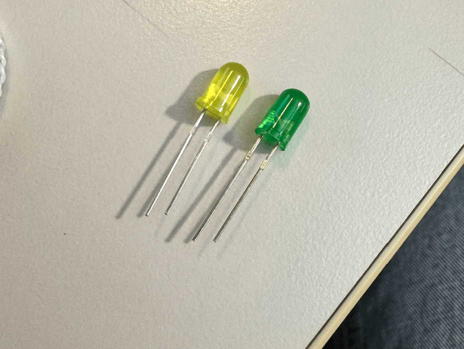
LED: A one-way light-producing component
-
Directional:
-
Longer leg (anode, +): connects to power
-
Shorter leg (cathode, -): connects to ground
-
-
Current limitation required: Operating voltage ≈ 2V
220Ω Resistor: Limits current flow
-
Calculation principle:
-
Using Ohm's Law (V = IR)
-
With 5V source, LED needs 2V
-
Remaining 3V handled by resistor
-
$R = V ÷ I \ R = 3V ÷ 0.015A \ R = 200Ω$
USB Connection:
-
Dual function:
-
Power: Provides stable 5V
-
Communication: Program upload and debugging
-
-
Through Arduino IDE:
-
Write code
-
Compile and check
-
Upload to board
-
Potentiometer (Optional): Adjustable resistor
- Control LED brightness
Steps
-
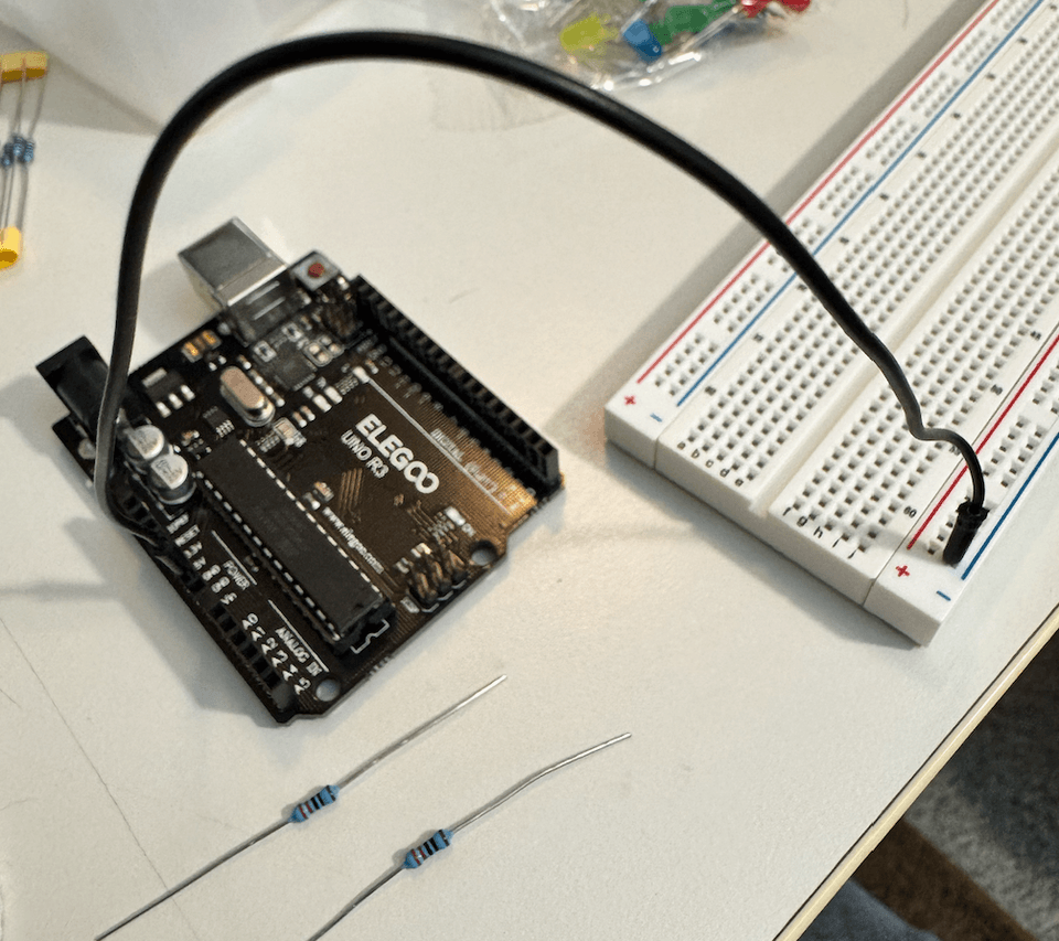
Connect Ground Wire
We connect black wire from Arduino GND to breadboard's negative rail. We do this because we want to establish common reference point (0V), creates return path for current flow, and complete circuit.
-
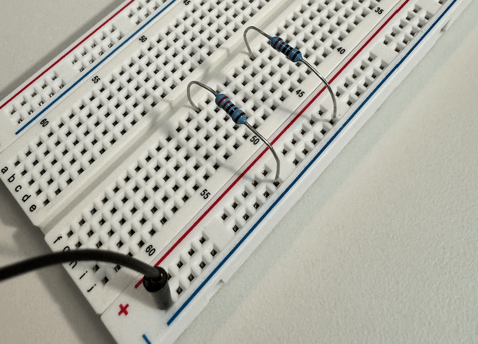
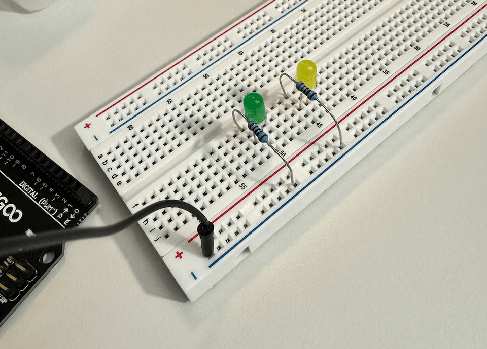
Place Resistor (220Ω)
Next we place resistor with one end in ground column. This can limits current to protect LED. We put one leg of the resistor in ground column, other leg bridges across central gap
-
Place LED
We connect LED with correct polarity. LED emits light in a specific direction (positive to negative). We conncet the short leg (-) to resistor to ensures current flows correct direction, and connect long leg (+) to separate row to be ready for control signal.
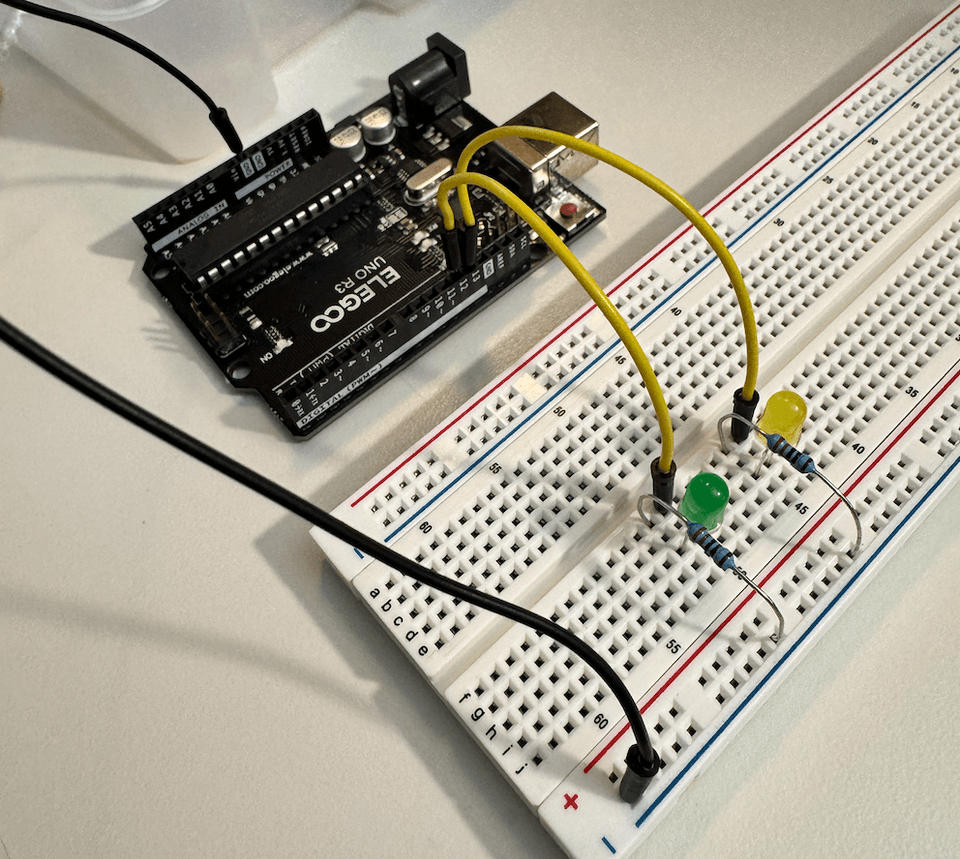
- Connect Digital Pin
Then we put Yellow wire from Arduino digital pin to LED. This allows programmatic control of LED. We chose digital pin 12 and 13 in this case. (We later change it to digital pin 11 and 12 because 13 has a default light on the controller.)
-
Power Up: Connect USB cable
Connet the USB cable to your computer, and this not only provides 5V power to Arduino controller, but also enables programming connection.
-
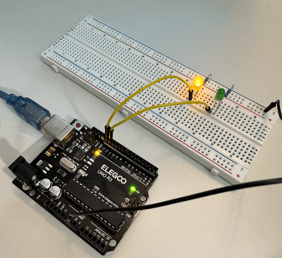
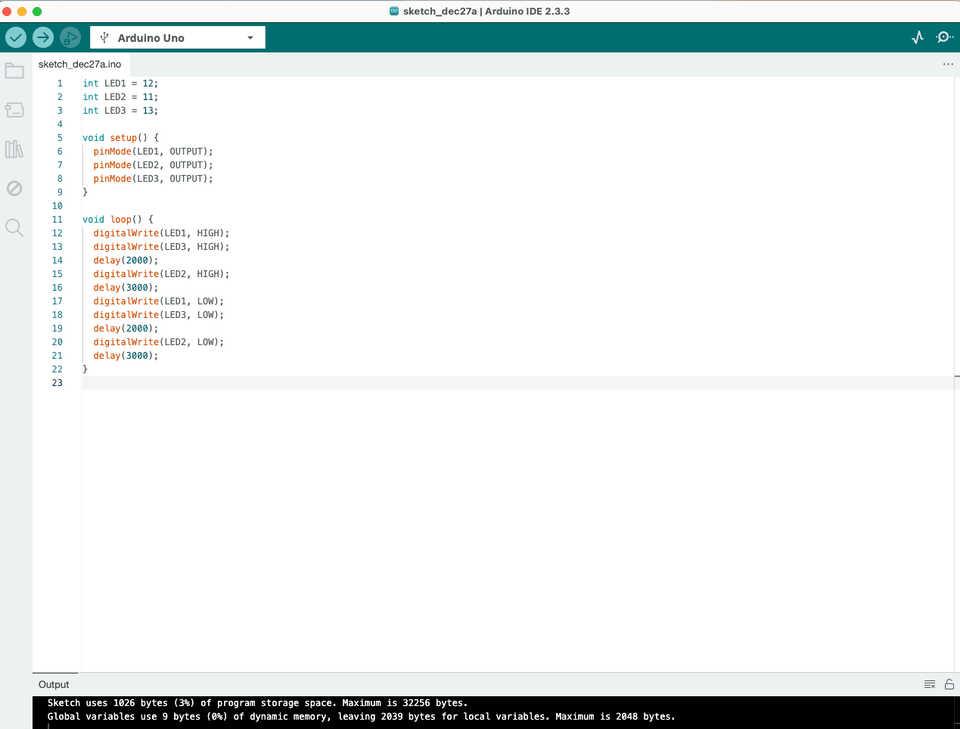
Program Upload: Write and upload basic LED control code
In the program, we can tell Arduino how to control the LED and set pin as output and create desired LED behavior.
LED1(pin 12) controls the green LEDLED2(pin 11) controls the yellow LEDLED3(pin 13) controls the built-in LED on boardOur sequence makes the green LED and built-in LED light up first for 2 seconds, then the yellow LED lights up for 3 seconds, creating an alternating pattern.
Total ON Time for Each LED:
-
LED1 and LED3: 5 seconds (2s + 3s)
-
LED2: 5 seconds (3s + 2s)
LED1: ON[=====]OFF----- // 5 seconds ONLED2: --ON[=====]OFF--- // 5 seconds ONLED3: ON[=====]OFF----- // 5 seconds ONTime: 0-2-3-4-5-6-7-8-9-10 (seconds) -
The whole circuit flow
Digital Pin (5V/0V) → LED (long leg +) → LED (short leg -) → Resistor → Ground
Summary
This LED control project provides an excellent introduction to both electronics and programming fundamentals. By building a simple circuit that controls multiple LEDs through an Arduino board, we learn several key concepts that form the foundation of electronics projects.
At the electronics level, we explore how electrical circuits work through practical implementation. We learn that electricity flows from high voltage to low voltage, requiring a complete circuit path. This understanding is reinforced as we build our circuit, starting with the ground connection, adding current-limiting resistors to protect our LEDs, and finally connecting our LEDs with proper polarity. Through this process, we see how each component plays a crucial role: the Arduino board provides power and control, the breadboard offers easy prototyping without soldering, resistors protect our components, and LEDs serve as visible output devices.
On the programming side, we learn how to communicate with hardware through code. The Arduino programming environment introduces us to basic programming concepts like setup and loop functions, digital pin control, and timing. We discover how to turn LEDs on and off programmatically, create sequences, and control timing using delay functions. This demonstrates the fundamental relationship between software commands and physical hardware responses.
Most importantly, this project teaches us the systematic approach needed for electronics projects. From careful circuit construction following a specific order (ground, resistors, LEDs, control signals) to methodical programming and testing, we learn the importance of proper planning and execution. These skills form a crucial foundation for more complex future projects, whether they involve different sensors, multiple outputs, or more sophisticated control systems.